Rankine cycle- in brief
September 10, 2008
A Rankine cycle describes a model of the operation of steam heat engines most commonly found in power generation plants. Common heat sources for power plants using the Rankine cycle are coal, natural gas, oil, and nuclear.
The Rankine cycle is sometimes referred to as a practical Carnot cycle as, when an efficient turbine is used, the TS diagram will begin to resemble the Carnot cycle. The main difference is that a pump is used to pressurize liquid instead of gas. This requires about 100 times less energy than that compressing a gas in a compressor (as in the Carnot cycle).
The working fluid in a Rankine cycle follows a closed loop and is re-used constantly.
One of the principal advantages it holds over other cycles is that during the compression stage relatively little work is required to drive the pump, due to the working fluid being in its liquid phase at this point. By condensing the fluid to liquid, the work required by the pump will only consume approximately 1% to 3% of the turbine power and so give a much higher efficiency for a real cycle.
Introduction-A shaper machine
September 5, 2008
A shaper is a machine tool used for shaping or surfacing metal and other materials.

Opration
shaper operates by moving a hardened cutting tool backwards and forwards across the workpiece. On the return stroke of the ram the tool is lifted clear of the workpiece, reducing the cutting action to one direction only.
The workpiece mounts on a rigid, box shaped table in front of the machine. The height of the table can be adjusted to suit this workpiece, and the table can traverse sideways underneath the reciprocating tool which is mounted on the ram, the table motion is usually under the control of an automatic feed mechanism which acts on the feedscrew. The ram slides back and forth above the work, at the front end of the ram is a vertical tool-slide that may be adjusted to either side of the vertical plane. This tool-slide holds the clapper box and toolpost from where the tool can be positioned to cut the straight, flat surface on the top of the workpiece. The tool-slide permits feeding the tool downwards to put on a cut it or may be set away from the vertical plane, as required.
The ram is adjustable for stroke and, due to the geometry of the linkage, it moves faster on the return (non-cutting) stroke than on the forward, cutting stroke. This action is via a slotted link or whitworth link.
Cutting fluid may be employed to improve the finish and prolong the tool’s life.
Degrees of Freedom of a Rigid Body
September 5, 2008
4.1.1 Degrees of Freedom of a Rigid Body in a Plane
The degrees of freedom (DOF) of a rigid body is defined as the number of independent movements it has.
Figure 4-1 shows a rigid body in a plane. To determine the DOF of this body we must consider how many distinct ways the bar can be moved. In a two dimensional plane such as this computer screen, there are 3 DOF. The bar can be translated along the x axis, translated along the y axis, and rotated about its centroid.

Figure 4-1 Degrees of freedom of a rigid body in a plane
4.1.2 Degrees of Freedom of a Rigid Body in Space
An unrestrained rigid body in space has six degrees of freedom: three translating motions along the x, y and z axes and three rotary motions around the x, y and z axes respectively.

Figure 4-2 Degrees of freedom of a rigid body in space
QUICK RETURN CRANK MECHANISM
September 5, 2008
|
A quick return mechanism such as the one seen opposite is used where there is a need to convert rotary motion into reciprocating motion. As the disc rotates the black slide moves forwards and backwards. Many machines have this type of mechanism and in the school workshop the best example is the shaping machine. |
|
||||

EXAMPLE – QUICK RETURN CRANK MECHANISM-SHAPER MACHINE
|
|||||


TOOL BIT(LATHE)
August 9, 2008
The term tool bit generally refers to a non-rotary cutting tool used in metal lathes, shape, and planer Such cutters are also often referred to by the set-phrase name of single-point cutting tool. The cutting edge is ground to suit a particular machining operation and may be resharpened or reshaped as needed. The ground tool bit is held rigidly by a tool holder while it is cutting.
Lathe machine – A father of machines….
August 1, 2008

Metal lathe are generic terms for any of a large class of lathes designed for precisely machining relatively hard materials. They were originally designed to machine metals; however, with the advent of plastics and other materials, and with their inherent versatility, they are used in a wide range of applications, and a broad range of materials. In . These rigid machine tools remove material from a rotating workpiece via the (typically linear) movements of various cutting tools, such as tool bits and drill bits.
These machines consist of, at the least, a headstock, bed, carriage and tailstock. These are the mostly used machines in the industry. Various types of jobs can be prepared on these machines.
Headstock

The headstock (H1) houses the main spindle (H4), speed change mechanism (H2,H3), and change gears (H10), The feedscrew (H8) is a long driveshaft that allows a series of gears to drive the carriage mechanisms.Both the feedscrew and leadscrew (H9) are driven by either the change gears (on the quadrant) or an intermediate gearbox known as a quick change gearbox (H6) or Norton gearbox.Tumbler gears (operated by H5) are provided between the spindle and gear train along with a quadrant plate that enables a gear train of the correct ratio and direction to be introduced.
The headstock is required to be made as robust as possible due to the cutting forces involved, which can distort a lightly built housing, and induce harmonic vibrations that will transfer through to the workpiece, reducing the quality of the finished workpiece.
Bed
The bed is a robust base that connects to the headstock and permits the carriage and tailstock to be aligned parallel with the axis of the spindle. This is facilitated by hardened and ground ways which restrain the carriage and tailstock in a set track. The carriage travels by means of a rack and pinion system, leadscrew of accurate pitch, or feedscrew.
Carriage

In its simplest form the carriage holds the tool bit and moves it longitudinally (turning) or perpendicularly (facing) under the control of the operator. The operator moves the carriage manually via the handwheel (5a) or automatically by engaging the feedscrew with the carriage feed mechanism (5c), this provides some relief for the operator as the movement of the carriage becomes power assisted. The handwheels (2a, 3b, 5a) on the carriage and its related slides are usually calibrated, both for ease of use and to assist in making reproducible cuts.
Tailstock

fig. shows tailstock with its different parts.
The tailstock is a toolholder directly mounted on the spindle axis, opposite the headstock. The spindle (T5) does not rotate but does travel longitudinally under the action of a leadscrew and handwheel (T1). The spindle includes a taper to hold drill bits, centers and other tooling. The tailstock can be positioned along the bed and clamped (T6) in position as required. There is also provision to offset the tailstock (T4) from the spindles axis, this is useful for turning small tapers.
The image shows a reduction gear box (T2) between the handwheel and spindle, this is a feature found only in the larger center lathes, where large drills may necessitate the extra leverage.
Psi- in brief….
July 29, 2008
The pound per square inch or, more accurately, pound-force per square inch (psi) is a unit of pressure or of stress. It is the pressure resulting from a force of one pound-force applied to an area of one square inch:
1 psi (6.89 kPa) : Pascal (Pa) is the SI unit of pressure.

pressure guage measuring pressure in psi
A compressed air car(or say future car)
July 29, 2008
A Compressed air car is an alternative fuel car that uses a motor powered by compressed air. The car can be powered solely by air, or combined (as in a hybrid electric vehicle) with gasoline/diesel/ethanol or electric plant and regenerative braking. Several companies including Tata Motors have signed a deal to produce the air cars by the summer of 2008.

- compressed air car

Compressed air cars are powered by engines, fueled by compressed air, which is stored in a tank under high pressure such as 30 MPa (4500 psi or 300 bar). The storage tank is likely to be made of carbon-fiber in order to reduce its weight while achieving the necessary strength. Instead of mixing fuel with air and burning it to drive pistons with hot expanding gases; compressed air cars use the expansion of compressed air to drive their pistons.
Advantages :
* Refueling can be done at home using an air compressor or at service stations.
*Compressed air engines reduce the cost of vehicle production by about 20%, because there is no need to build a cooling system, spark plugs, transmission, axles, starter motor.
*Compressed-air vehicles emit no pollutants.
*Lighter vehicles would result in less wear on roads.
LCD screen….
July 29, 2008
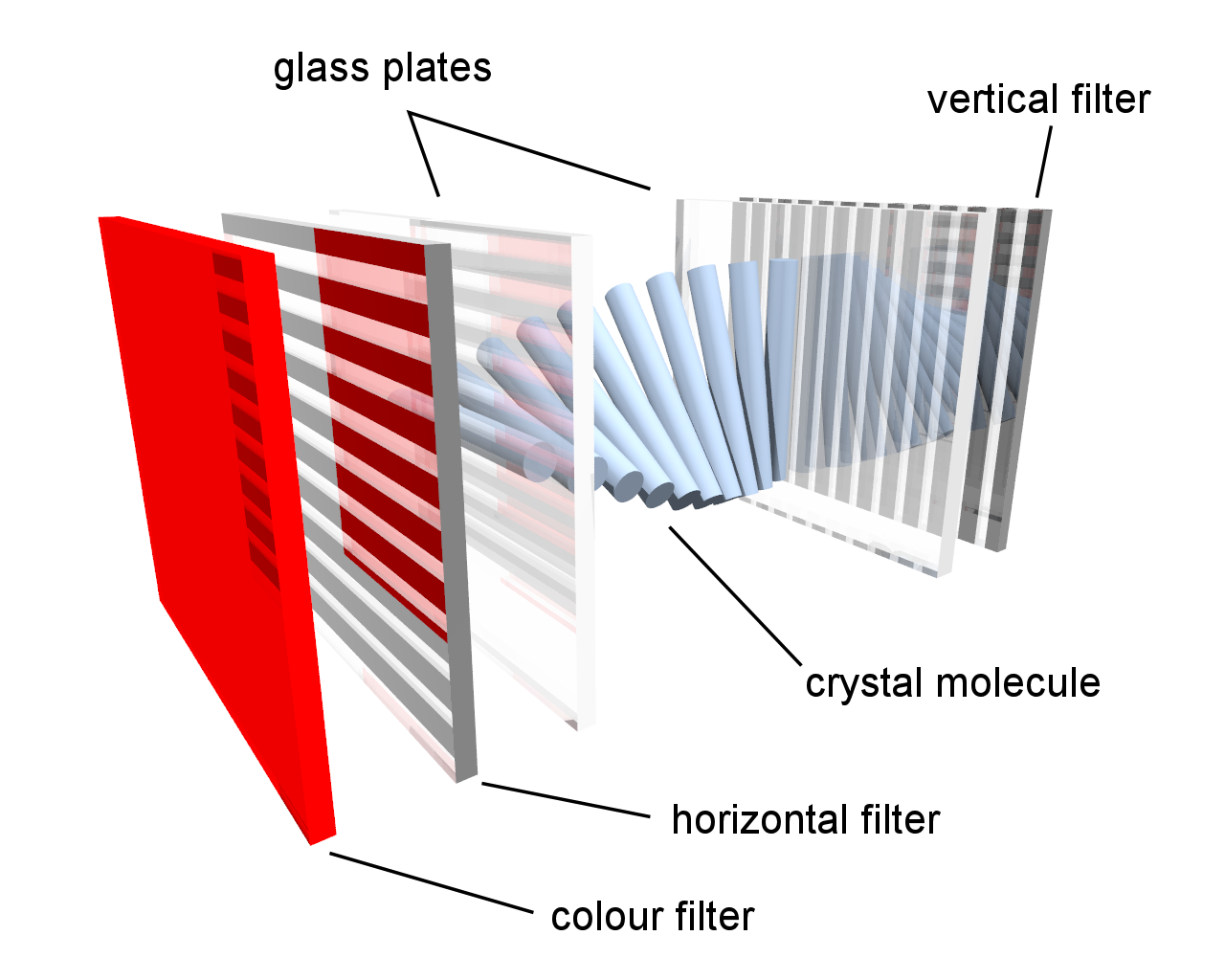
A liquid crystal display (LCD) is a thin, flat display device made up of any number of color or monochrome pixels arrayed in front of a light source or reflector. It is often utilized in battery-powered electronic devices because it uses very small amounts of electric power.
- Polarizing filter film with a vertical axis to polarize light as it enters.
- Glass substrate with ITO electrodes. The shapes of these electrodes will determine the dark shapes that will appear when the LCD is turned on or off. Vertical ridges etched on the surface are smooth.
- Twisted nematic liquid crystals.
- Glass substrate with common electrode film (ITO) with horizontal ridges to line up with the horizontal filter.
- Polarizing filter film with a horizontal axis to block/pass light.
- Reflective surface to send light back to viewer. (In a backlit LCD, this layer is replaced with a light source.)
Fuel cell – in brief…….
July 29, 2008
A fuel cell is an electrochemical conversion device. It produces electricity from fuel (on the anode side) and an oxidant (on the cathode side), which react in the presence of an electrolyte. The reactants flow into the cell, and the reaction products flow out of it, while the electrolyte remains within it. Fuel cells can operate virtually continuously as long as the necessary flows are maintained.

fuel cell
Fuel cells are different from electrochemical cell batteries in that they consume reactant, which must be replenished, whereas batteries store electrical energy chemically in a closed system. Additionally, while the electrodes within a battery react and change as a battery is charged or discharged, a fuel cell’s electrodes are catalytic and relatively stable.
Many combinations of fuel and oxidant are possible. A hydrogen cell uses hydrogen as fuel and oxygen as oxidant. Other fuels include hydrocarbons and alcohols. Other oxidants include air, chlorine and chlorine dioxide.
